|
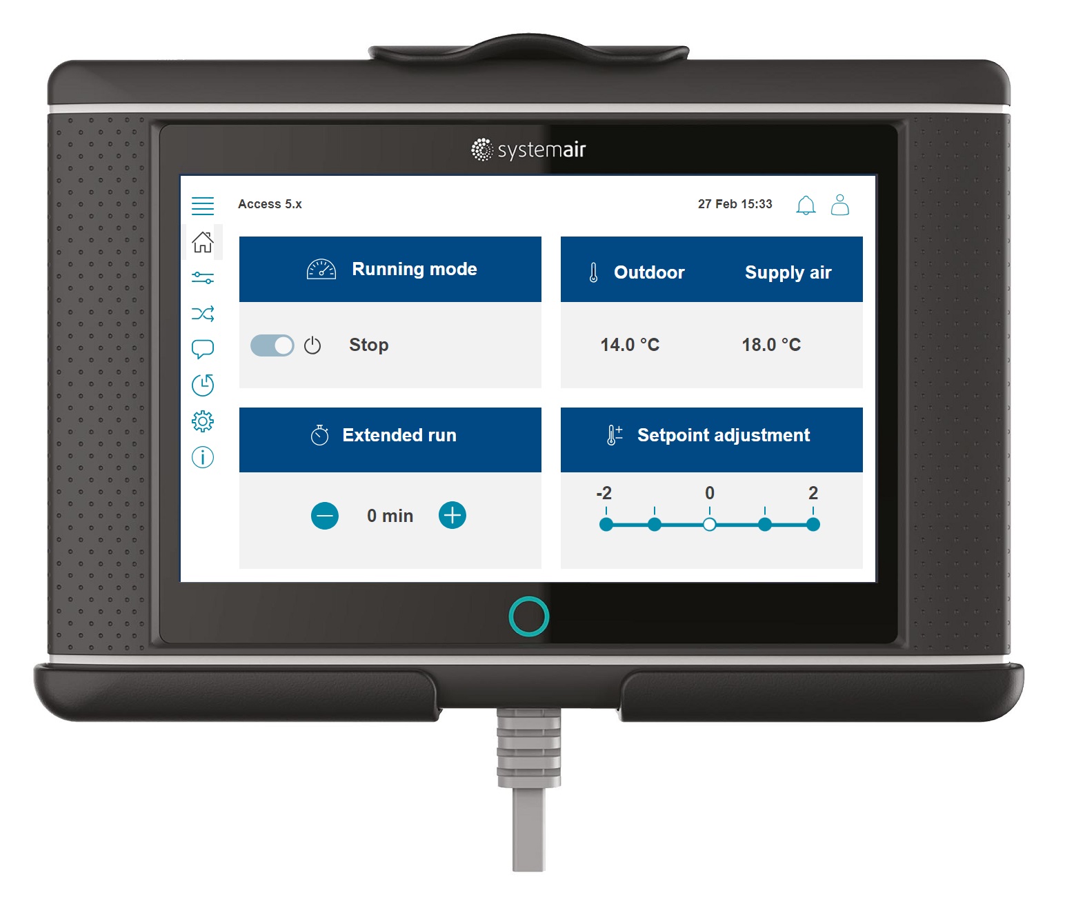
Access 5.4 |
Flowchart |
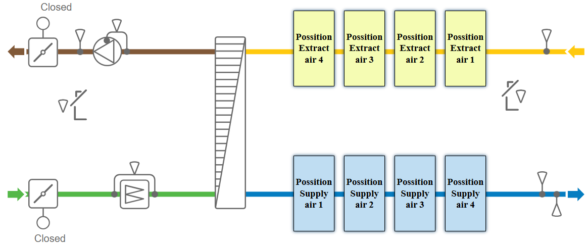
Version 5.4 and later of Access introduce a more flexible component representation within the flowchart. There are four available positions for adding components to the supply-air path and four positions for the extract-air path. This means that elements such as heaters, coolers, and humidifiers are no longer restricted to predefined locations; they can be assigned to any available position to reflect the actual physical installation.
However, exceptions apply when certain critical functions are enabled. For example, if a safety-damper module is activated, both position 4 locations are automatically reserved to display the associated safety-module components in the flowchart. In such cases, these positions become unavailable for user assignment.
Flowchart setup |
|||
Variable |
Available options & Selection |
Note |
|
Flowchart setup |
|||
Configuration > Functions > Flow chart setup |
|||
Flow chart |
| Off | On | |
Flowchart can be disabled. If disabled (Off) the flow chart icon will be unavailable |
|
Outdoor air/Supply air damper placement |
| Outdoor air | Supply air | Outdoor air + Supply air | |
Select the right positioning of the dampers |
|
Extract air/Exhaust air damper placement |
| Exhaust air | Extract air | Exhaust air + Extract air | |
||
Position Supply air 1 |
Available options vary depending on the functions that are enabled and configured |
Select the function to be displayed for each position in the flowchart (see image below). |
|
Position Supply air 2 |
|||
Position Supply air 3 |
|||
Position Supply air 4 |
|||
Position Extract air 1 |
|||
Position Extract air 2 |
|||
Position Extract air 3 |
|||
Position Extract air 4 |
|||
|
|||