|
Access 5.x |
Reversible heat pump - defrosting free (configuration example) |
The air handling unit section with heat pump is a separate section, containing a fully integrated, complete reversible heat pump system (heating and cooling).
All refrigerant system components are fully integrated into the unit. The refrigerant is evaporated and condensed directly in the integrated coils, and the capacity is controlled automatically and steeples between 15 and 100 %.
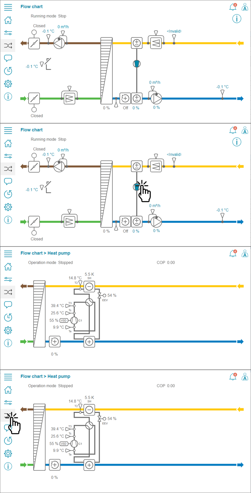
The performance overview of the modbus connected heat pump unit can be over accessed via main flow chart.

The table below shows a configuration example of the single stage Reversible Heat pump.
Modbus connected Reversible Heat Pump |
|||||
Variable |
Available options & Selection |
Note |
|||
Sequence selection |
|||||
Configuration > Functions > Function activation > Heating/Cooling sequence setup |
|||||
Sequence for heating |
|...| SEQ-G Heating 2 | SEQ-H |...| |
||||
Sequence for cooling |
|...| SEQ-G | SEQ-H Cooling 2 |... | |
||||
Sequence settings |
|||||
Configuration > Functions > Function activation > Heating/Cooling sequence setup > Heating 2 |
|||||
Type of sequence |
|Cooling | Exchanger | Heating | Damper | | Fan setpoint compensation | |
||||
Type of heater |
| Water | Electric| DX | Combi coil | |
||||
Type of feedback |
| None | Alarm | Run indication | |
||||
Digital start output |
| No | Yes | |
||||
Run indication from DX-compressor |
| No | Yes | |
||||
Defrost indication from DX-machine |
| No | Yes | |
||||
Sequence output when recirculation/support |
| 0% | 100% | Auto | |
||||
Sequence output min limit |
[0] % |
||||
Sequence output max limit |
[100] % |
||||
Sequence output when the unit is stopped |
[0] % |
||||
Configuration > Functions > Function activation > Heating/Cooling sequence setup > Cooling 2 |
|||||
Type of sequence |
|Cooling | Exchanger | Heating | Damper | Fan setpoint compensation | |
||||
Type of cooler |
| Water | DX | DX with exchanger control | |
||||
Type of feedback |
| None | Alarm | Run indication | |
||||
Digital start output |
| No | Yes | |
||||
Run indication from DX-compressor |
| No | Yes | |
||||
Defrost indication from DX-machine |
| No | Yes | |
||||
Sequence output when recirculation/support |
| 0% | 100% | Auto | |
||||
Sequence output min limit |
[0] % |
||||
Sequence output max limit |
[100] % |
||||
Sequence output when the unit is stopped |
[0] % |
||||
Changeover settings |
|||||
Configuration > Functions > Function activation > Heating/Cooling sequence setup > Changeover settings |
|||||
Name |
GXR-HP-DF |
||||
Original name |
Changeover 1 |
||||
Changeover sequence for heating |
… | Heating 2 | … |
||||
Changeover sequence for cooling |
… | Cooling 2 | … |
||||
Type of changeover |
... | Reversible heat pump Supply air - Extract air | ... |
||||
Configuration of Modbus connected Heat pump |
|||||
Configuration > System settings > Communication Devices > Device 20 |
|||||
Type |
| Disabled | ... | Heat pump (Modbus) | |
Select type of the connected device (Heat pump) |
|||
Brand |
| 1 Circuit | 1 Circuit with Boost heater | 2 Circuit | 2 Circuit with Boost heater | |
Select type of the Heat pump |
|||
Address |
[0] > [54] |
Enter the same address as configured in the Heat pump |
|||
Function |
| Select | Exp1 | Exp2 | Exp3 |... |
Assign function (Spare expansion unit number) |
|||
Heat pump sequence |
| Disabled | Changeover 1 | Changeover 2 | |
Select the changeover sequence to be related to the operation of the heat pump |
|||
Name |
[Device 20] > [Heat pump] |
Change default name to more informative |
|||
Communication type |
| RTU | TCP | |
- |
|||
Communication port |
| Ext-link | BMS | Int-link 1 & 2 | |
Select port for communication to the device |
|||
Flowchart Settings |
|||||
Configuration > Functions > Flow chart setup |
|||||
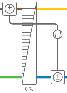
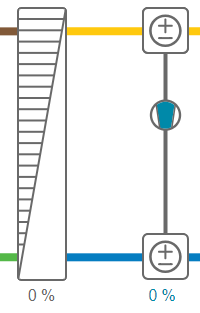
Position Exchanger-Supply air |
| None | | Reversible heat pump Supply air - Extract air | |
flowchart representation for | None |
|
flowchart representation for | Reversible heat pump Supply air - Extract air |
|
||
PID Settings |
|||||
Configuration > PID controllers > Heating 2 |
|||||
P-band |
[10] oC |
Adjust the PID settings if necessary |
|||
I-time |
[100] s |
||||
D-time |
[0] s |
||||
Configuration > PID controllers > Cooling 2 |
|||||
P-band |
[10] oC |
Adjust the PID settings if necessary |
|||
I-time |
[100] s |
||||
D-time |
[0] s |
||||
Configuration settings of the heat pump |
|||||
Configuration > Functions > Heat pump |
|||||
Heat pump request mode |
| Reversible | Only cooling | Only heating | |
||||
Increase air flow extract air fan to avoid heat pump - high pressure alarm |
| No | Auto | |
||||
Heat pump reduce mode - delay time before next sequence |
[60] s |
||||
Configuration > Functions > Heat pump > Flow compensation curve |
|||||
Flow |
Compensation |
Settings available for edit only for Admin" access level |
|||
Lowest points |
[2000] m3/h |
[-1.1] |
|||
Middle points |
[4160] m3/h |
[-0.5] |
|||
Highest points |
[6318] m3/h |
[0.0] |
|||
Operational settings |
|||||
Data & Settings > Temperature control > Changeover 1 |
|||||
Delay time PID-Lock |
[180] s |
||||
Min run time DX machine |
[600] s |
||||
Blocking-time |
[60] min |
||||
Data & Settings > Temperature control > Changeover 1 > Heating 2 |
|||||
Digital start output start point |
[15] % |
Output of the supply controller to start and stop the heater |
|||
Digital start output stop point |
[10] % |
||||
Heating mode blocked when Extract air temperature < |
[15] oC |
Default = 15 oC (+1 oC hyst = 16 oC) |
|||
Heating mode blocked when outdoor temperature > |
[17] oC |
Default = 17 oC (-1 oC hyst = 16 oC) |
|||
Block if supply air fan output signal < |
[0] % |
||||
Data & Settings > Temperature control > Changeover 1 > Cooling 2 |
|||||
Digital start output start point |
[15] % |
Output of the supply controller to start and stop the DX cooler |
|||
Digital start output stop point |
[10] % |
||||
Heating mode blocked when outdoor temperature < |
[14] oC |
Default = 14 oC (+1 oC hyst = 15 oC) |
|||
Block if supply air fan output signal < |
[0] % |
||||


